Minor connectors are those components that serve as the connecting link between the major connector or the base of a removable partial denture and other components of the prosthesis, such as the clasp assembly, indirect retainers, occlusal rests, or cingulum rests.
Functions
- Joins different parts of the denture with the major connector.
- Transfers functional stress to the abutment teeth.
- Transfers the effect of the retainers, rests and stabilising components throughout the prosthesis.
Design consideration
The design for minor connectors can be discussed under four categories:
- Minor connectors that join clasp assemblies to major connectors.
- Minor connectors that join indirect retainers or auxiliary rests to major connectors.
- Minor connectors that join denture bases to major connectors.
- Minor connectors that serve as approach arms for vertical projection/bar-type clasps.
Minor connectors joining clasp assemblies to major connectors
- Must have sufficient bulk to ensure rigidity, but should not be objectionable to the patient.
- When located on proximal surfaces of teeth adjacent to the edentulous areas, the minor connector should be broad buccolingually, but thin mesiodistally, making it easier to place prosthetic tooth in a natural position.
- When a clasp assembly must be positioned on a tooth that is not adjacent to an edentulous space, the minor connector should be positioned in the associated lingual embrasure, where it will be least noticeable to the tongue. It should never be placed on the convex lingual surface of a tooth.
- It should conform to the interdental embrasure, passing vertically from the major connector so that the gingival crossing is abrupt and covers as little of the gingival tissue as possible.
- It should be thickest toward the lingual surface, and tapering toward the contact area.
- The deepest part of the interdental embrasure should have been blocked out to avoid interference during placement and removal, and to avoid any wedging effect on the contacted teeth.
Minor connectors joining indirect retainers or auxiliary rests to major connectors
- Should form right angles with the corresponding major connectors, but junctions should be gently curved to prevent stress concentration.
- Should be positioned in lingual embrasures to disguise their bulk and promote patient comfort.
Minor connectors joining denture bases to major connectors
-
Must be strong enough to anchor a denture base to the denture framework, with minimal interference with the arrangement of the prosthetic teeth.
-
Maxillary arch : The minor connector should be extended as far posteriorly as is practical, since the distal extension base must extend the entire length of the ridge and should cover the tuberosity.
-
Mandibular arch : Minor connector should extend two-thirds the length of the edentulous ridge, as the distal extension base must cover the retromolar pad.
-
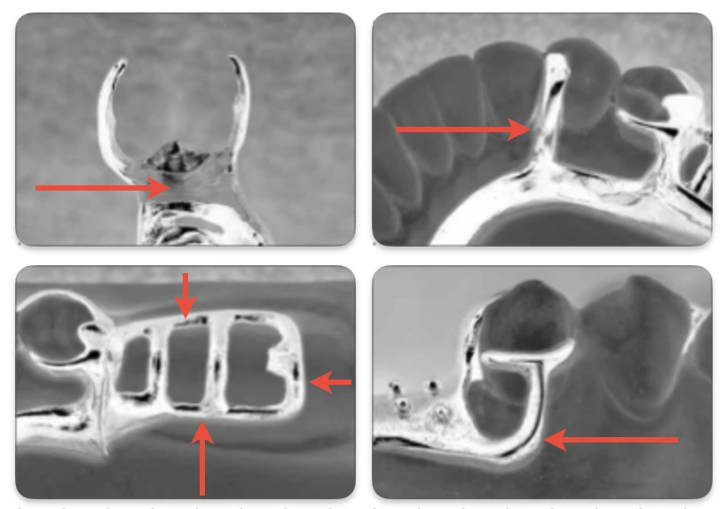
These minor connectors can be described in three groups. An open latticework or ladder type of design is preferable and is conveniently made by using preformed 12-gauge half-round and 18-gauge round wax strips.
- Open construction
- Mesh construction
- Bead, wire or nailhead components on a metal base.
Open construction
-
Consists of longitudinal and transverse struts that form a ladder-like network.
-
Provides the strongest attachment of acrylic resin to the denture framework, and can be used whenever multiple teeth are to be replaced.
-
Also facilitates relining and rebasing of removable partial dentures.
-
Longitudinal strut
- Mandibular arch : One should be positioned buccal to the crest of the ridge and the other lingual to the crest.
- Maxillary arch : One should be positioned buccal to the ridge crest, while the border of the major connector generally acts as the second longitudinal strut.
-
Transverse strut : Ideally it should be designed to pass between the necks of the artificial teeth.
-
The longitudinal and transverse struts should be encircled by the acrylic resin to provide retention to the denture base. This can be achieved by providing suitable relief using wax (24-26 gauge) to the areas of master cast (that are to feature open construction) during framework fabrication process.
Mesh construction
-
May be compared to a rigid metallic screen, with channels that pass through the connector.
-
The channels are intended to permit acrylic resin penetration, which allows encirclement of the minor connector with the resin and mechanical retention of the denture base.
-
Relief and border extension is similar to open construction.
-
Drawback :
- Difficulty in packing of acrylic resin: Increased pressure is needed to force resin through the small holes in the minor connector. Insufficient packing pressure may result in inadequate resin penetration and a weak attachment to the framework.
- Mesh must cover the entire ridge crest and cannot be limited to those areas between the necks of prosthetic teeth. Hence, it may interfere with the arrangement of prosthetic teeth.
Bead, nailhead, or wire construction
- Often used in conjunction with metal denture bases, where in the metal bases are cast to fit directly against the underlying soft tissues, and resin is attached to the free surface of such bases.
- Retention is gained by encompassment of surface projections.
- No relief is provided beneath these minor connectors, as the metal bases are in direct contact with the underlying tissue.
- Fabrication : Beads and nailheads may be created by placing resin beads on the appropriate segments of the wax pattern, while, wire construction involves casting or soldering of irregular wire forms to a metal base.
Minor connectors serving as approach arms for vertical projection/bar-type clasps
- These components support direct retainers (clasps) and therefore must exhibit some degree of flexibility. These are the only minor connectors that are not required to be rigid.
- Approach the tooth from an apical direction rather than an occlusal direction.
- The approach arm should display a smooth, even taper from its origin to its terminus.
- When it gives rise to a clasp arm, the connector should be tapered to the tooth below the origin of the clasp.
- If no clasp arm is formed (as when a bar clasp arm originated elsewhere), the connector should be tapered to a knife-edge the full length of its buccal aspect.
- It must not cross a soft tissue undercut, and for this reason its use is contraindicated in some instances.
Tissue stops (Cast stops)
Refers to small area at the free end of the minor connector that contacts the master cast. These are required in case of distal extension prosthesis to minimise or eliminate bending of the framework, since, the use of relief in open and mesh construction produces a minor connector that is supported at only one end, which can lead to bending of the minor connector when load is applied.
- A cast stop is created by removing a small square of relief wax (2x2 cm) where the posterior strut of the minor connector crosses the center of the ridge.
- They provide stability to the framework during the stages of transfer and processing.
- They are particularly useful in preventing distortion of the framework during acrylic-resin processing procedures.
- Tissue stops can engage buccal and lingual slopes for stability.
Finishing Lines
Finish lines refer to the interfaces formed at the resin-metal joints in RPDs with an acrylic resin denture bases.
- The minor connector must be joined to the major connector with sufficient bulk to avoid fracture, and the acrylic resin denture base must join the major connector in a smooth, even fashion.
Internal finish line
- Positioned on the inner or tissue surfaces.
- Formed as a result of relief wax placed on the edentulous ridges of a master cast prior to duplication.
- The margins of the relief wax should be sharp and well defined.
External finish lines
- Located on the outer surfaces of major connectors, and formed by the placement and carving of wax during fabrication.
- Must be sharp and slightly undercut to help lock the acrylic resin to the major connector.
- The internal angle formed at the junction should not be greater than 90 degrees.
Location
- The location of the finishing line at the junction of the major and minor connectors should be based on restoration of the natural palate shape, with consideration given to the location of the replacement teeth.
- Finishing line located too far medially: The natural contour of the palate will be altered by the thickness of the junction and the acrylic resin supporting the artificial teeth.
- Finishing line located too far buccally: Will be most difficult to create a natural contour of the acrylic resin on the lingual surface of the artificial teeth.
References
- Stewart’s Clinical Removable Partial Prosthodontics (4th edition), Rodney D. Phoenix, David R. Cagna, Charles F. DeFreest, Quintessence Books.
- McCracken’s Removable Partial Prosthodontics (13th edition), Alan B. Carr DMD MS, David T. Brown DDS MS, Elsevier.
- The image used is derived from Stewart’s Clinical Removable Partial Prosthodontics (4th edition).
*This article is an excerpt from the above mentioned books and Medical Sutras does not make any ownership and affiliation claims.